Engineering Reference Design · Prototype Validation Required
Relay Control Board Design
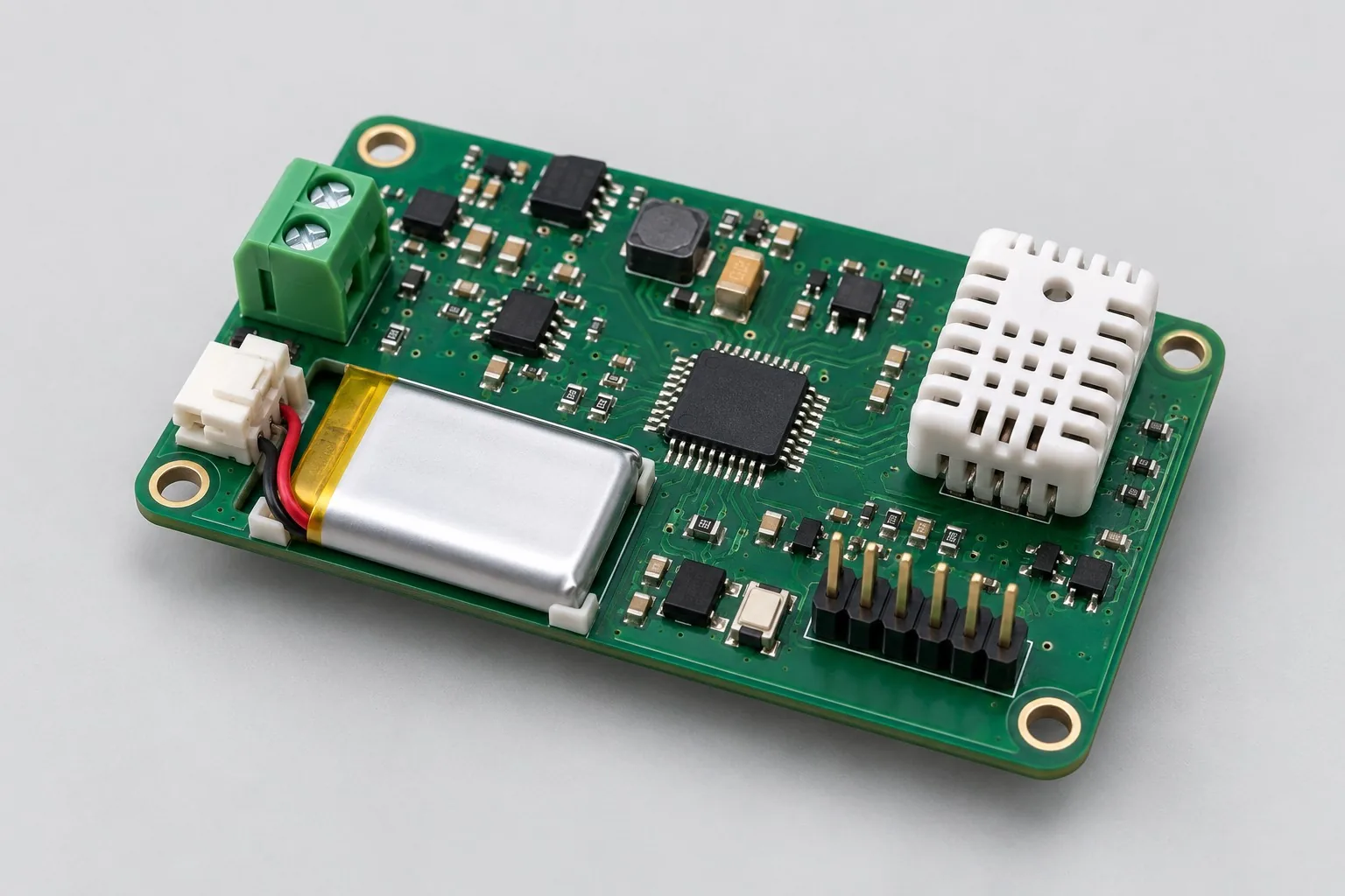
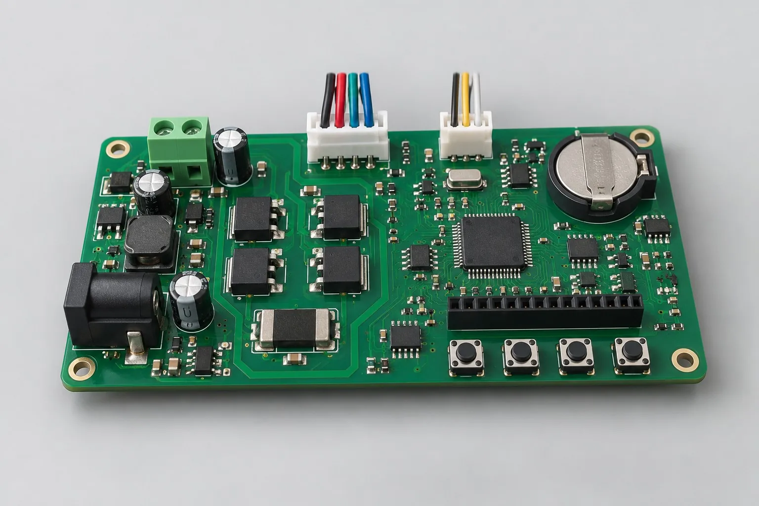
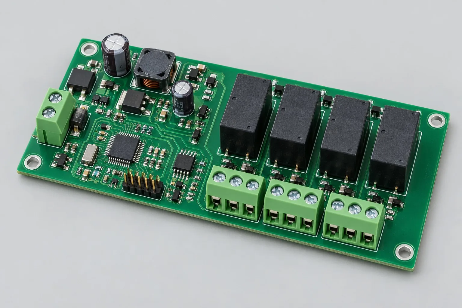
Relay control board design: divide 24V four-channel control into power/drives, RS485 commands, and loaded prototypes. Existing schematics can first undergo contact-protection and interlock review; if only switching validation is needed, freeze loads and build prototypes first, then expand remote protocols later.
- Finished Product Function
- 4-channel relay switching with status readback
- Operating Input
- 24V DC nominal; reverse-polarity protection and input fuse position
- Layer Stackup Plan
- Start with 2-layer FR-4; separate contact and logic regions
- Communication Interface
- 1 RS485 port, with Modbus RTU as a protocol option
- Core Component
- STM32-class MCU + RS485 transceiver + low-side drivers