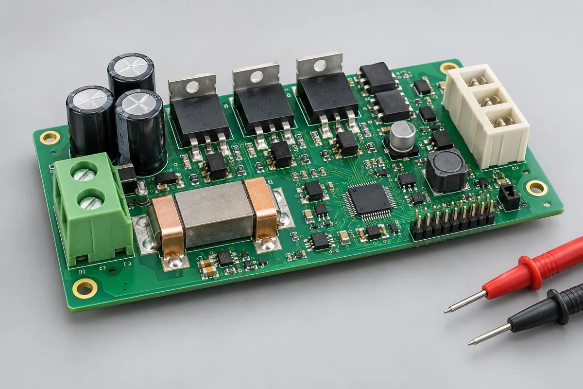
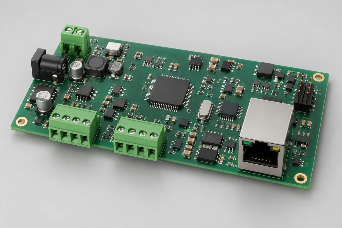
Prototype PCB assembly with a defined learning objective
Request prototype PCBA through KFPCBA to assemble a released revision and check the functions assigned to this build. We coordinate PCB fabrication, component sourcing and assembly; circuit development, debugging and specialist verification need their own agreed scope.
Start by stating whether the samples will check fit, power-up, an interface, a measurement chain or the manufacturing route. The objective determines materials, test access and the records needed for the next revision.
Prepare a build package around the prototype task
| Input | Decision to make | Keep with the build |
|---|
| BOM and variants | Full part numbers, approved alternatives, DNP positions and ownership | One released BOM and variant identifier. |
| Fabrication and assembly files | Board construction, placement, orientations, mechanical restrictions and test points | Matching Gerber/drill, placement and drawing revisions. |
| Programming | Supplied image, interface, configuration and recovery responsibility | Firmware identifier and programming instruction. |
| Validation | Stimuli, loads, limits, instruments and fixture owner | Test procedure, conditions, observations and unresolved issues. |
Separate assembly acceptance from circuit debugging
Assembly checks whether the populated board follows the released package and agreed workmanship requirements. Debugging an unproven design asks a different question. Record temporary jumpers, replaced components and firmware changes so successful bench work can be converted into a controlled revision.
The BOM and placement checklist helps prevent file mismatches. Use test planning to allocate the required checks rather than assuming a programmed board is functionally accepted.
Choose material and fixture work for this stage
Specify who supplies bare boards, scarce components, custom connectors and fixtures. Package condition, moisture sensitivity, partial quantities and replenishment decisions matter when only limited parts are available. Do not silently replace an unavailable component to keep a prototype moving.
Separate reusable stencils or fixtures from temporary debug arrangements. List engineering, procurement, assembly, programming, calibration and test work visibly in the quotation; the PCBA cost guide provides that comparison structure.
Release the next revision from actual findings
- Identify the boards, hardware revision, fitted alternatives and software used in each observation.
- State which original requirements were tested and which remain open.
- Carry approved component and wiring changes into schematic, BOM, PCB and assembly documentation.
- Agree the additional checks needed before repeat low-volume builds.
For an initial enquiry, describe the prototype objective and the documents you have. Use the project inquiry before the package is complete, or the engineering RFQ when files are ready.